|
|
| (5 intermediate revisions by the same user not shown) |
| Line 1: |
Line 1: |
| − | <section begin="History" />
| + | {{:AXEL_Lite_SOM/AXEL_Lite_Hardware/Power_and_Reset/JTAG}} |
| − | {| style="border-collapse:collapse; "
| |
| − | !colspan="4" style="width:100%; text-align:left"; border-bottom:solid 2px #ededed"|History
| |
| − | |-
| |
| − | !style="border-left:solid 2px #73B2C7; border-right:solid 2px #73B2C7;border-top:solid 2px #73B2C7; border-bottom:solid 2px #73B2C7; background-color:#73B2C7; padding:5px; color:white"|Issue Date
| |
| − | !style="border-left:solid 2px #73B2C7; border-right:solid 2px #73B2C7;border-top:solid 2px #73B2C7; border-bottom:solid 2px #73B2C7; background-color:#73B2C7; padding:5px; color:white"|Notes
| |
| − | |-
| |
| − | |style="border-left:solid 2px #73B2C7; border-right:solid 2px #73B2C7;border-top:solid 2px #73B2C7; border-bottom:solid 2px #73B2C7; background-color:#edf8fb; padding:5px; color:#000000"|{{oldid|11422|2020/11/07}}
| |
| − | |style="border-left:solid 2px #73B2C7; border-right:solid 2px #73B2C7;border-top:solid 2px #73B2C7; border-bottom:solid 2px #73B2C7; background-color:#edf8fb; padding:5px; color:#000000"|New layout documentation
| |
| − | |-
| |
| − | ! style="border-left:solid 2px #73B2C7; border-right:solid 2px #73B2C7;border-top:solid 2px #73B2C7; border-bottom:solid 2px #73B2C7; background-color:#ededed; padding:5px; color:#000000" |2021/09/22
| |
| − | ! style="border-left:solid 2px #73B2C7; border-right:solid 2px #73B2C7;border-top:solid 2px #73B2C7; border-bottom:solid 2px #73B2C7; background-color:#ededed; padding:5px; color:#000000" |Add JTAG EVB connector
| |
| − | |-
| |
| − | |}
| |
| − | <section end="History" />
| |
| − | __FORCETOC__
| |
| − | <section begin="Body" />
| |
| − | | |
| − | ==On board JTAG connector==
| |
| − | | |
| − | JTAG signals are routed to a dedicated connector on the AXEL Lite PCB. | |
| − | | |
| − | The connector is placed on the top side of the PCB, at the upper-right corner (please see the picture below).
| |
| − | | |
| − | [[File:Axellite-jtag-conn.png|500px|frameless|border]]
| |
| − | | |
| − | === J7 - SOM Connector's pinout ===
| |
| − | | |
| − | J7 footprint mates with Samtec FSI-110-03-G-S connector. The following table reports the connector's pinout:
| |
| − | | |
| − | [[File:AXEL Lite-EVB-JTAG-connector.png|thumb|center| 500px|JTAG connector]]
| |
| − | | |
| − | {| class="wikitable"
| |
| − | |-
| |
| − | !Pin#
| |
| − | !Pin name
| |
| − | !Function
| |
| − | !ARM-20 JTAG
| |
| − | !Notes
| |
| − | |-
| |
| − | |1 || DGND || -
| |
| − | |4,6,8,10,12,14,16,18,20|| For example documented on [https://www2.lauterbach.com/pdf/app_arm_jtag.pdf#page=3 Lauterbach specification]
| |
| − | |-
| |
| − | |2 || JTAG_TCK || -
| |
| − | |9|| -
| |
| − | |-
| |
| − | |3 || JTAG_TMS || -
| |
| − | |7|| 10K pull-up to 3V3 (BOARD_PGOOD driven signal)
| |
| − | |-
| |
| − | |4 || JTAG_TDO || -
| |
| − | |13|| 10K pull-up to 3V3 (BOARD_PGOOD driven signal)
| |
| − | |-
| |
| − | |5 || JTAG_TDI || -
| |
| − | |5|| 10K pull-up to 3V3 (BOARD_PGOOD driven signal)
| |
| − | |-
| |
| − | |6 || JTAG_nTRST || -
| |
| − | |3 (*) || 10K pull-up to 3V3 (BOARD_PGOOD driven signal)
| |
| − | |-
| |
| − | |7 || CPU_PORn || -
| |
| − | |15 (*)|| -
| |
| − | |-
| |
| − | |8 || N.C. || -
| |
| − | ||| -
| |
| − | |-
| |
| − | |9 || N.C. || -
| |
| − | ||| -
| |
| − | |-
| |
| − | |10 || JTAG_VREF || -
| |
| − | |1|| 3V3 (BOARD_PGOOD driven signal)
| |
| − | |-
| |
| − | |}
| |
| − | (*) keep the possibility to be unconnected
| |
| − | | |
| − | === JD1 - EVB Connector's pinout ===
| |
| − | | |
| − | JD1 is a 10x1x2.54mm pinhole header. The following table reports the connector's pinout:
| |
| − | | |
| − | [[File:SBC-AXEL-JTAG.png|thumb|center| 500px|EVB JTAG connector]]
| |
| − | | |
| − | {| class="wikitable"
| |
| − | |-
| |
| − | !Pin#
| |
| − | !Pin name
| |
| − | !Function
| |
| − | !Notes
| |
| − | |-
| |
| − | |1 || DGND || -
| |
| − | |
| |
| − | |-
| |
| − | |2 || JTAG_TCK || -
| |
| − | | -
| |
| − | |-
| |
| − | |3 || JTAG_TMS || -
| |
| − | | 10K pull-up to 3V3 (BOARD_PGOOD driven signal)
| |
| − | |-
| |
| − | |4 || JTAG_TDO || -
| |
| − | | 10K pull-up to 3V3 (BOARD_PGOOD driven signal)
| |
| − | |-
| |
| − | |5 || JTAG_TDI || -
| |
| − | | 10K pull-up to 3V3 (BOARD_PGOOD driven signal)
| |
| − | |-
| |
| − | |6 || JTAG_nTRST || -
| |
| − | | 10K pull-up to 3V3 (BOARD_PGOOD driven signal)
| |
| − | |-
| |
| − | |7 || JTAG_nRST || -
| |
| − | | -
| |
| − | |-
| |
| − | |8 || N.C. || -
| |
| − | | -
| |
| − | |-
| |
| − | |9 || N.C. || -
| |
| − | | -
| |
| − | |-
| |
| − | |10 || JTAG_VREF || -
| |
| − | |
| |
| − | |-
| |
| − | |}
| |
| − | | |
| − | ----
| |
| − | | |
| − | [[Category:AXEL Lite]]
| |
| History
|
| Issue Date
|
Notes
|
| 2020/09/22
|
New documentation layout
|
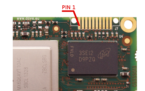
JTAG signals are routed to a dedicated connector on the AXEL Lite PCB.
The connector is placed on the top side of the PCB, at the upper-right corner (please see the picture below).
J7 - SOM Connector's pinout[edit | edit source]
J7 footprint mates with Samtec FSI-110-03-G-S connector. The following table reports the connector's pinout:
| Pin#
|
Pin name
|
Function
|
ARM-20 JTAG
|
Notes
|
| 1 |
DGND |
-
|
4,6,8,10,12,14,16,18,20 |
For example documented on Lauterbach specification
|
| 2 |
JTAG_TCK |
-
|
9 |
-
|
| 3 |
JTAG_TMS |
-
|
7 |
10K pull-up to 3V3 (BOARD_PGOOD driven signal)
|
| 4 |
JTAG_TDO |
-
|
13 |
10K pull-up to 3V3 (BOARD_PGOOD driven signal)
|
| 5 |
JTAG_TDI |
-
|
5 |
10K pull-up to 3V3 (BOARD_PGOOD driven signal)
|
| 6 |
JTAG_nTRST |
-
|
3 (*) |
10K pull-up to 3V3 (BOARD_PGOOD driven signal)
|
| 7 |
CPU_PORn |
-
|
15 (*) |
-
|
| 8 |
N.C. |
-
|
|
-
|
| 9 |
N.C. |
-
|
|
-
|
| 10 |
JTAG_VREF |
-
|
1 |
3V3 (BOARD_PGOOD driven signal)
|
(*) keep the possibility to be unconnected

