RIALTO SBC/pdf
Getting started[edit | edit source]
Unboxing[edit | edit source]
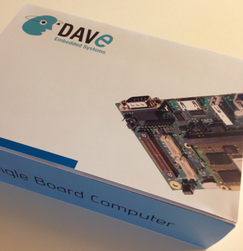
Once you've received the RIALTO SBC, please open the box and check the kit contents with the packing list included in the box, using the table here below.
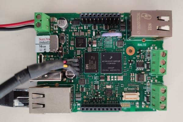
The hardware components (SOM, carrier boards and display) are pre-assembled, as shown in the picture below:
Box Contents[edit | edit source]
The following table lists the kit components:
| Component | Description |
|---|---|
| RIALTO Single board computer | |
| AC/DC Single Output Wall Mount adapter Output: +12V – 2.0 A | |
| FTDI TTL/USB cable (TTL-232RG-VIP-WE) | |
| MicroSDHC card |
Order codes[edit | edit source]
The RIALTO SBC order code can be composed using the Part number composition page
microSD Layout[edit | edit source]
The microSD provided with the kit is used to store:
- a bootable partition (mmcblk0p1, vfat) containing:
- binary images (u-boot and kernel images)
- root file system partition (mmcblk0p2, ext4)
Connections[edit | edit source]
This section describes how to quickly start the RIALTO SBC:
The system is programmed to automatically boot Linux at power up, loading the bootloader, the kernel and device tree image and the root file system from the SD card memory.
To connect to the system:
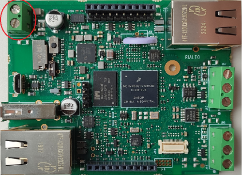
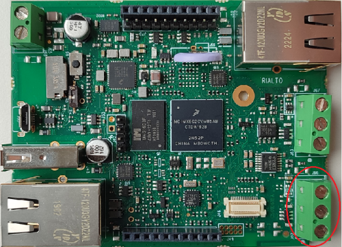
- wire a 12Vcc power supply to J58 connector's terminals
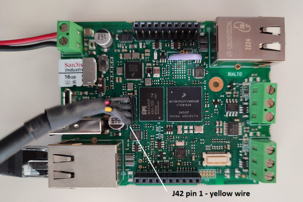
- connect the USB to TTL UART adapter to the J42 connector on the SBC and connect the USB side connector to a USB port on your computer
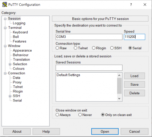
- start your favorite terminal emulator software on PC (eg: PuTTY, Minicom, ...); communication parameters are 115200,N,8,1
- (optional) connect the ethernet cable from your LAN hub/switch to the J16 RJ45 connector
- start SSH, using the following parameters:
- ip address: 192.168.0.89
- username: root
- empty password
- start SSH, using the following parameters:
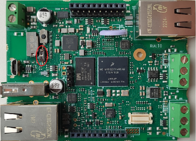
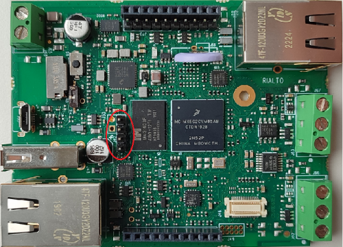
Warning: please, pay attention to the debug cable header connection, see the picture here below:
First boot[edit | edit source]
Once power has been applied, U-Boot bootloader will be executed and the debug messages will be printed on the serial console. U-Boot automatically runs the autoboot macro, that loads the kernel/dtb and launches it with the options for mounting the root file system from the SD card.
At the end of the boot process, a demo application is launched and you can interact with the system using the touchscreen. The Linux shell is available on the serial console. Moreover, both telnet and ssh services are available to connect to the system through the network.
Serial console[edit | edit source]
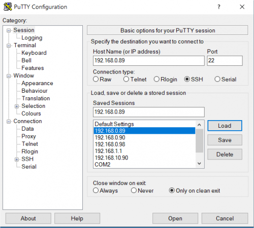
A simple Windows serial and SSH/telnet client and terminal can be downloaded from here.
The following picture shows the serial setup for connecting to the EVK:
once selected the COM[x] serial port, click the Open button which starts the terminal. Once powered, the EVK shows the U-boot debug messages printed on the serial console.
Connecting through SSH[edit | edit source]
The following picture shows the SSH connection to the EVK:
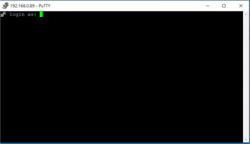
once selected the IP address, click the Open button which starts the terminal. Once connected, the EVK shows the linux kernel prompt login for inserting the login:
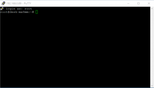
Then use the root login username without password:
Boot Configurations[edit | edit source]
RIALTO SBC is built upon i.MX6UL SOC processor.
The following sections detail boot configuration options, which differ depending on the SBC.
Available options[edit | edit source]
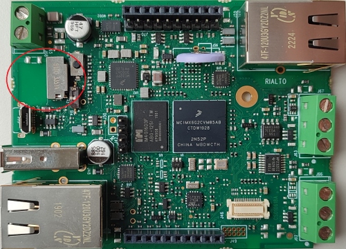
Boot modes can be selected by S14 switch which acts directly on SYSBOOT configuration pins.
S14 switch correctly configure the internal pins allowing different boot modes.
| Boot options | S14 ON | S14 OFF |
|---|---|---|
| Boot storage | SD | NAND |
Reset Button[edit | edit source]
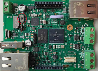
RIALTO SBC has a pushbutton connected - by default mounting option - PMIC_PWRON signal which drives a SOC hardware reset.
S11 is the hardware reset button.
General Information[edit | edit source]
Product Highlights[edit | edit source]
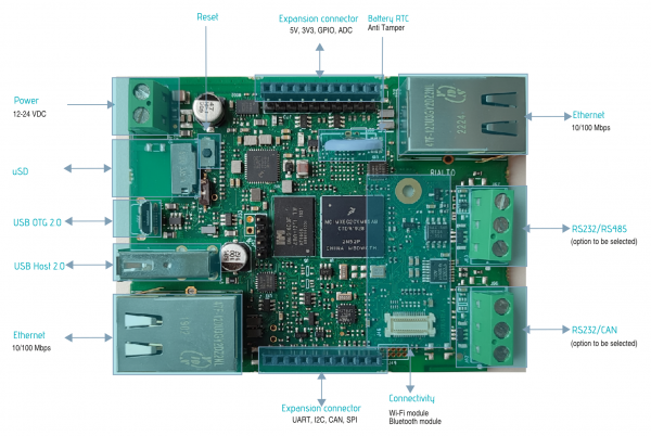
The RIALTO SBC platform presented here provides a compact solution for any industry and can be easily interfaced with Plant Automation Control thanks to IEC-61131 SW language environment and/or other plug-ins like nodeJS and Java JVM.
The following table summarizes the main hardware and software features available with RIALTO SBC:
Hardware[edit | edit source]
| Subsystem | Characteristics |
|---|---|
| CPU | NXP i.MX6UL core |
| Serial Ports | 1x RS232 or RS485 1x RS232 or CAN |
| Ethernet | 2x 10/100Mbps |
| USB | 1x USB 2.0 Host port
2x USB 2.0 OTG |
| RTC | Battery backup with anti-tamper |
| Connectivity | (optional) Bluetooth and Wi-Fi |
| LED and Buttons | (optional) membrane with up to 6 LED and 2 buttons |
| Expansion connectors | (optional) UART, I2C, SPI, CAN, ADC, GPIOs connections |
| PSU | 12 to 24V DC |
| Mechanical Dimensions | 87x68mm - Standard DIN (4modules) |
Software[edit | edit source]
| Subsystem | Options |
|---|---|
| Operating System | Linux |
| Distribution | Yocto, Debian, Buildroot |
| Applications | SoftPLC, IoT runtime, nodeJS |
Block diagram[edit | edit source]
The following picture shows a simplified block diagram of the RIALTO SBC.
Main functional subsystems and interfaces are depicted.
The heart of the RIALTO SBC is the i.MX6UL NXP System On Chip: please refer to the following Product Highlights page for the product highlights information.
Here below a summary for the main characteristics of the SBC.
Features Summary[edit | edit source]
| Feature | Specifications |
|---|---|
| Supported SOC | NXP i.MX6UL |
| Serial Ports | 1x UART RS232 or RS485 1x UART RS232 or CAN 1x UART RS232 on pin strip (debug port) |
| Connectivity | up to 2x Fast Ethernet on RJ45 connector 1x CAN port with PHY (optional) DWS Wireless module (optional) |
| Storage | 1x microSD slot |
| USB | 1x USB 2.0 Host port 1x USB OTG port |
| Miscellaneous | Mezzanine connectors with GPIOs |
Electrical, Mechanical and Environmental Specifications[edit | edit source]
| Electrical / Mechanicals | Specifications |
|---|---|
| Supply voltage | 12 to 24 V |
| Dimensions | 86 mm x 68 mm |
| Weight | 107,6 g |
| Operating Temperature | -5 to 65 °C |
Expansion boards[edit | edit source]
XUAL[edit | edit source]
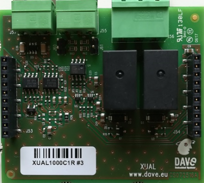
XUAL is an expansion board that can be plugged directly into RIALTO mezzanine connectors. It adds some peripherals for extending the IoT capabilities of RIALTO SBC.
Block Diagram[edit | edit source]
The following picture shows XUAL's block diagram:
Connection layout[edit | edit source]
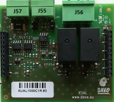
The following picture shows XUAL's connection layout:
Connectors pinout[edit | edit source]
J55 - Digital intput[edit | edit source]
J55 is a Phoenix 1803280 MC 1.5/3-G-3.81 3x3.81mm connector. The two digital input can sense a 12V or 24V level input signals.
The following table reports the connector's pinout:
| Pin# | Pin function | RIALTO GPIO | Pin Notes |
|---|---|---|---|
| 1 | IN_0 | J61.8 (GPIO1_IO04) | |
| 2 | IN_1 | J61.9 (GPIO1_IO05) | |
| 3 | GND |
J56 - Relays output[edit | edit source]
J56 is a Phoenix 1757255 MSTBA 2.5/3-G-5.08 3x5mm connector.
The following table reports the connector's pinout:
| Pin# | Pin function | RIALTO GPIO | Pin Notes |
|---|---|---|---|
| 1 | RL0_NO | J61.6 (GPIO1_IO02) | N.O. |
| 2 | RELAY_COMMON | - | common signal for RL0 and RL1 N.O. relays |
| 3 | RL1_NO | J61.7 (GPIO1_IO03) | N.O. |
J57 - PT100 intput[edit | edit source]
J57 is a Phoenix 1803280 MC 1.5/3-G-3.81 3x3.81mm connector. The PT100 resistance cover the entire range -200°C +600°C.
The following table reports the connector's pinout:
| Pin# | Pin function | Pin Notes |
|---|---|---|
| 1 | Rw1 | |
| 2 | Rw2 | |
| 3 | Rw3 |
RTIN[edit | edit source]
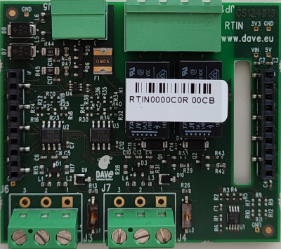
RTIN is an expansion board that can be plugged directly on RIALTO mezzanine connectors. It adds some peripherals for extending the IoT capabilities of RIALTO SBC.
Block Diagram[edit | edit source]
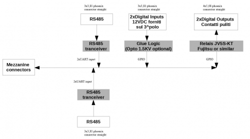
The following picture shows RTIN's block diagram:
Connection layout[edit | edit source]
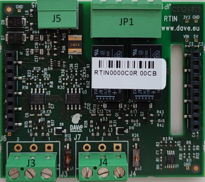
The following picture shows RTIN's connection layout:
Connectors pinout[edit | edit source]
J3 - UART2[edit | edit source]
J3 is a Phoenix 282837-3 3x50.8mm connector.
The following table reports the connector's pinout:
| Pin# | Pin function | Pin Notes |
|---|---|---|
| 1 | RS485_A | MAX13487 pin 6 |
| 2 | RS485_B | MAX13487 pin 6 |
| 3 | GND | connected to DGND |
J4 - UART5[edit | edit source]
J4 is a Phoenix 282837-3 3x50.8mm connector.
The following table reports the connector's pinout:
| Pin# | Pin function | Pin Notes |
|---|---|---|
| 1 | RS485_A | MAX13487 pin 6 |
| 2 | RS485_B | MAX13487 pin 6 |
| 3 | GND | connected to DGND |
JP1 - Relays output[edit | edit source]
J4 is a Phoenix 1757491 MSTBA 2,5/ 4-G 4x5mm connector.
The following table reports the connector's pinout:
| Pin# | Pin function | RIALTO GPIO | Pin Notes |
|---|---|---|---|
| 1 | RL1.1 | J61.5 (GPIO1_IO01) | N.O. |
| 2 | RL1.2 | N.O. | |
| 3 | RL2.1 | J61.6 (GPIO1_IO02) | N.O. |
| 4 | RL1.2 | N.O. |
J5 - Digital input[edit | edit source]
J5 is a Phoenix 1803280 MC 1,5/ 3-G-3,81 3x3.81mm connector.
The following table reports the connector's pinout:
| Pin# | Pin function | RIALTO GPIO | Pin Notes |
|---|---|---|---|
| 1 | DI1 | J60.8 (MEZZANINE_GP1) | 1K ohm pull-down |
| 2 | DI2 | J60.9 (MEZZANINE_GP2) | 1K ohm pull-down |
| 3 | VIN | connected to VIN va MF-SMDF050 1.2A resettable fuse |
Interfaces and Connectors[edit | edit source]
Power Supply interface[edit | edit source]
Description[edit | edit source]
The Power Supply interface is available on the SBC connector J68.
J68 is a two pins MSTBA 2.5/2-G-5.08 Phoenix connector.
Signals[edit | edit source]
The following table describes the interface signals:
| Pin# | Pin function | Pin Notes |
|---|---|---|
| 1 | VIN | +[12-24 V] |
| 2 | DGND | Ground |
JTAG interface[edit | edit source]
Description[edit | edit source]
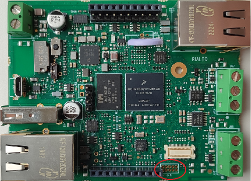
JTAG signals are routed to a dedicated connector on the RIALTO SBC PCB.
The connector is placed near the J60 mezzanine connector and J46 WiFi connector (please see the picture below).
Signals[edit | edit source]
The following table describes the interface signals:
| Pin# | Pin name | ARM-20 JTAG | Notes |
|---|---|---|---|
| 1 | DGND | Ground | 4,6,8,10,12,14,16,18,20 |
| 2 | JTAG_TCK | 9 | |
| 3 | JTAG_TMS | 7 | |
| 4 | JTAG_TDO | 13 | |
| 5 | JTAG_TDI | 5 | |
| 6 | JTAG_nTRST | 3 | keep the possibility to be unconnected |
| 7 | CPU_PORn | 15 | keep the possibility to be unconnected |
| 8 | JTAG_MOD | Internally used as GPIO for USB OTG power enable in Host mode | |
| 9 | n.c. | ||
| 10 | JTAG_VREF | 1 | 3V3 internal pull-up |
Ethernet interface[edit | edit source]
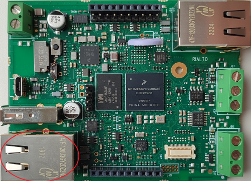
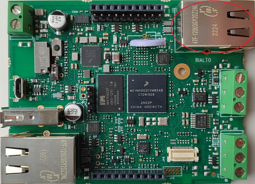
RIALTO SBC has two Ethernet interfaces:
- eth0 on J16 (labelled as Ethernet 1)
- eth1 on J59 (labelled as Ethernet 2)
Description[edit | edit source]
The Ethernet interfaces are available at the connectors J16 and J59. Primary interface is on J16.
J16 and J59 are a RJ45 shielded connectors with link/activity led.
Signals[edit | edit source]
The following table describes the interface signals:
- J16
| Pin# | Pin name | Pin Notes |
|---|---|---|
| 1 | ETH1_TX_P | - |
| 2 | TCT | TX center tap |
| 3 | ETH1_TX_M | - |
| 4 | ETH1_RX_P | - |
| 5 | RCT | RX center tap |
| 6 | ETH1_RX_M | - |
| 7 | NC | - |
| 8 | PCB_GND_RNG | CHS_GND |
| 9 | NC | - |
| 10 | NC | - |
| 11 | ETH1_LED | - |
| 12 | 3V3_IO | - |
| 13, 14 | PCB_GND_RNG | Connector Shield |
- J59
| Pin# | Pin name | Pin Notes |
|---|---|---|
| 1 | ETH2_TX_P | - |
| 2 | TCT | TX center tap |
| 3 | ETH2_TX_M | - |
| 4 | ETH2_RX_P | - |
| 5 | RCT | RX center tap |
| 6 | ETH2_RX_M | - |
| 7 | NC | - |
| 8 | PCB_GND_RNG | CHS_GND |
| 9 | NC | - |
| 10 | NC | - |
| 11 | ETH2_LED | - |
| 12 | 3V3_IO | - |
| 13, 14 | PCB_GND_RNG | Connector Shield |
Device mapping[edit | edit source]
The network interfaces mapped as follows:
- J16 is
eth0device in Linux. - J59 is
eth1device in Linux.
Device usage[edit | edit source]
The peripherals use the standard kernel interface and network protocol stack.
Console interface[edit | edit source]
Description[edit | edit source]
The Console interface is available on the RIALTO SBC to the following connector: J42 is a Phoenix 4x1x2.54mm pin header connector. On this connector is mapped the console interface (UART1).
Signals[edit | edit source]
The following tables describe the interfaces signals:
J42[edit | edit source]
| Pin# | Pin name | Pin function | Pin Notes |
|---|---|---|---|
| 1 | TX | UART1_TX | LVTTL signal |
| 2 | RX | UART1_RX | LVTTL signal |
| 3 | VDD | 3V3 | powered by internal PMIC |
| 4 | DGND | GND |
Device mapping[edit | edit source]
UART1 is mapped to /dev/ttymxc0 device in Linux. The peripheral is used as the default serial console, both for the bootloader and the kernel.
Device usage[edit | edit source]
To connect to the debug serial port:
- connect an UART transceiver (eg: TTL-232RGVIP-WE) to J42 and to a workstation
- leave J42.3 unconnected if the transceiver is self powered
- start your favorite terminal emulator software on PC (eg: PuTTY); communication parameters are: 115200,8N1
UARTs interface[edit | edit source]
Description[edit | edit source]
The UARTs interfaces available on the RIALTO SBC are mapped to the following connectors:
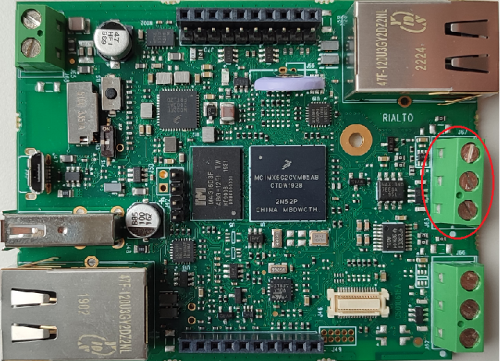
- J66 is a Phoenix 282837-3 3x50.8mm connector. On this connector are mapped these instances: UART3 or CAN.
- J67 is a Phoenix 282837-3 3x50.8mm connector. On this connector are mapped these instances: UART3 or UART8.
Signals[edit | edit source]
The following tables describe the interfaces signals:
J66[edit | edit source]
| Pin# | Pin name | Pin function | Pin Notes |
|---|---|---|---|
| 1 | EXT1_P1 | RS232_RX or CAN_P | optional RS232 or CAN port |
| 2 | EXT1_P2 | RS232_TX or CAN_M | optional RS232 or CAN port |
| 3 | EXT1_GND | GND | connected to DGND directly or to PCN GND ring via RC filter |
J67[edit | edit source]
| Pin# | Pin name | Pin function | Pin Notes |
|---|---|---|---|
| 1 | EXT2_P1 | RS232_RX or RS485_A | optional RS232 or RS485 port |
| 2 | EXT2_P2 | RS232_TX or RS485_B | optional RS232 or RS485 port |
| 3 | EXT2_GND | GND | connected to DGND directly or to PCN GND ring via RC filter |
Device mapping[edit | edit source]
RS232 is UART3 and it is mapped to /dev/ttymxc2 device in Linux
RS485 is UART8 and it is mapped to /dev/ttymxc7 device in Linux
CAN is FLEXCAN1 and it is mapped to can0 device in Linux
Device usage[edit | edit source]
The RS232, RS485 and CAN use the standard protocols.
CAN interface[edit | edit source]
Description[edit | edit source]
The CAN interface is optionally available on RIALTO SBC at the connector J66.
- J66 is a Phoenix 282837-3 3x50.8mm connector. On this connector are mapped these instances: UART3 or CAN.
CAN interface is connected to the i.MX6UL FLEXCAN controller.
Signals[edit | edit source]
The following table describes the interface signals:
| Pin# | Pin name | Pin function | Pin Notes |
|---|---|---|---|
| 1 | EXT1_P1 | RS232_RX or CAN_P | optional RS232 or CAN port |
| 2 | EXT1_P2 | RS232_TX or CAN_M | optional RS232 or CAN port |
| 3 | EXT1_GND | GND | connected to DGND directly or to PCN GND ring via RC filter |
Device mapping[edit | edit source]
CAN devices are mapped to can0 device in Linux. The device mapping depends on the device tree configuration.
Device usage[edit | edit source]
The peripheral can be configured using ifconfig and ip link utilities and can be tested with the can-utils utilities.
micro SD interface[edit | edit source]
Description[edit | edit source]
The SD interface is available on RIALTO SBC at the connector J43.
J43 is a Micro-SD card header. This interface is connected to the SD1 controller of the i.MX6UL CPU.
Signals[edit | edit source]
The following table describes the interface signals:
| Pin# | Pin name | Pin function | Pin Notes |
|---|---|---|---|
| 1 | SD_DAT2 | Data 2 | |
| 2 | SD_DAT3 | Data 3 | |
| 3 | SD_CMD | CMD | |
| 4 | 3V3_IO | +3.3 V | |
| 5 | SD_CLK | Clock | |
| 6, 11 | DGND | Ground | |
| 7 | SD_DAT0 | Data 0 | |
| 8 | SD_DAT1 | Data 1 | |
| 9, 10 | PCB_GND_RNG | Shield | |
| 12 | SD_DET | Card detect |
Device mapping[edit | edit source]
The microSD card is mapped to /dev/mmcblk0.
Device usage[edit | edit source]
The device can be mounted/accessed as a standard block device in Linux.
USB ports[edit | edit source]
Description[edit | edit source]
RIALTO SBC provides two USB ports, one HOST and one OTG:
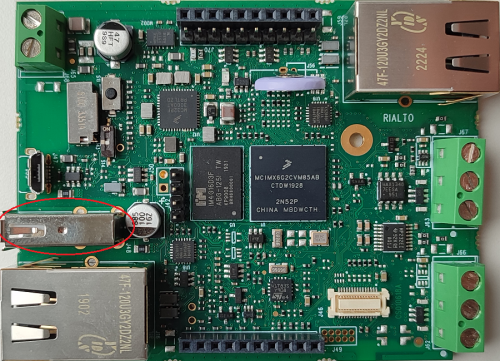
- J48 is a standard USB HOST 2.0 Type A connector
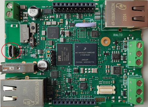
- J55 is a micro-AB type receptacle for a USB OTG connection: this interface can operate in Host mode and Device (peripheral) mode
Signals[edit | edit source]
The following table describes the interface signals:
USB HOST[edit | edit source]
| Pin# | Pin name | Pin function | Pin Notes |
|---|---|---|---|
| 1 | USB_HOST_5V | VBUS | |
| 2 | USB_DM1 | USB Host Data - | |
| 3 | USB_DP1 | USB Host Data + | |
| 4 | DGND | Ground | |
| 5, 6, 7, 8 | PCB_GND_RNG | Shield |
USB OTG[edit | edit source]
| Pin# | Pin name | Pin function | Pin Notes |
|---|---|---|---|
| 1 | VBUS_OTG_5V | VBUS | |
| 2 | USB_DM2 | USB OTG Data - | |
| 3 | USB_DP2 | USB OTG Data + | |
| 4 | PA8 | USB OTG ID | |
| 5 | GND | Ground | |
| 6, 7, 8 | PCB_GND_RNG | Shield |
Device mapping[edit | edit source]
The USB Host port can be used under Linux for connecting USB peripheral devices: the related peripheral driver has to be integrated into the Linux kernel.
The USB OTG feature can be easily tested using the Mass Storage Gadget driver.
RTC[edit | edit source]
Description[edit | edit source]
RIALTO SBC uses an external I2C RTC device, i.e. M41T83SQA6F.
An external lithium battery (like Panasonic ML-1220/V1AN rechargeable battery) can be optionally mounted on RIALTO SBC.
Signals[edit | edit source]
The following table describes the interface signals:
| Pin# | Pin name | Pin function | Pin Notes |
|---|---|---|---|
| 1 | RTC_LICELL | VBAT | coin cell battery network has to be properly configured for lithium battery recharge current |
| 2 | GND | Ground |
Device mapping[edit | edit source]
RTC is mapped to /dev/rtc0 device in Linux.
Device usage[edit | edit source]
The peripheral can be accessed through the date and hwclock linux commands.
Wifi/Bluetooth interface[edit | edit source]
DWM and DWS are DAVE WiFi addons that provide WiFi 802.11 bgn and Bluetooth connectivity.
Description[edit | edit source]
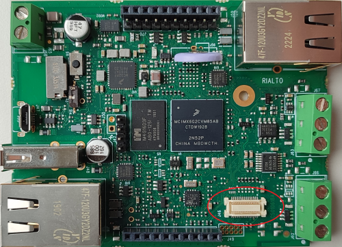
The Wifi/Bluetooth interfaces are available on RIALTO SBC at the connector J46.
J46 is a 30-pins 0.50mm Pitch SlimStack™ Receptacle. This connector is dedicated to the DWM/DWS optional add-on module.
Signals[edit | edit source]
The following table describes the interface signals:
| Pin# | Pin name | Pin function | Pin Notes |
|---|---|---|---|
| 1, 2 | 5V | Power supply | |
| 3, 4 | 3.3V | Power supply | |
| 5, 6, 9, 10, 19 | DGND | Ground | |
| 7 | TIWI_MMC2_CMD | ||
| 8 | TIWI_MMC2_CLK | ||
| 11 | TIWI_MMC2_DAT0 | ||
| 13 | TIWI_MMC2_DAT1 | ||
| 15 | TIWI_MMC2_DAT2 | ||
| 17 | TIWI_MMC2_DAT3 | ||
| 21 | UART2_RX | Used only for BT peripheral | |
| 23 | UART2_CTS | Used only for BT peripheral | |
| 24 | TIWI_BT_F5 | Used only for BT peripheral | |
| 25 | UART2_TX | Used only for BT peripheral | |
| 26 | TIWI_BT_F2 | Used only for BT peripheral | |
| 27 | UART2_RTS | Used only for BT peripheral | |
| 28 | TIWI_IRQ | ||
| 29 | TIWI_BT_EN | Used only for BT peripheral | |
| 30 | TIWI_EN | ||
| 12, 14, 16, 18, 20, 22 | N.C. | Not connected |
WiFi[edit | edit source]
Device mapping[edit | edit source]
The WiFi peripheral is mapped to the corresponding wlan<0> device in Linux. The network peripheral is visible under the ifconfig network configuration utility.
Device usage[edit | edit source]
The peripheral uses the standard kernel interface and network protocol stack.
Bluetooth[edit | edit source]
Device mapping[edit | edit source]
The BT peripheral is mapped to the /dev/ttymxc1 serial port in Linux. It can be mounted as an hci device with the hci tools commands.
Device usage[edit | edit source]
The peripheral is used by the standard kernel interface and BlueZ protocol stack.
Mezzanine Connectors[edit | edit source]
Description[edit | edit source]
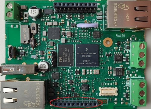
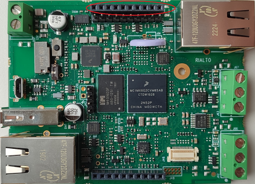
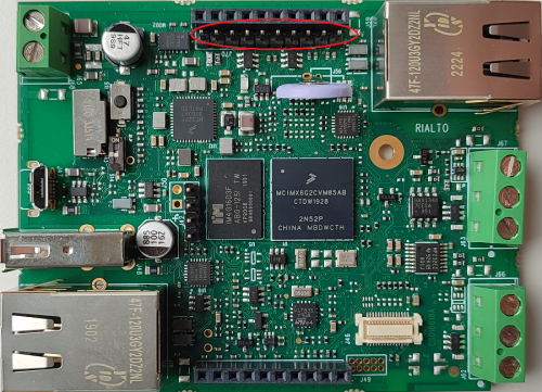
RIALTO SBC has two mezzanine expansion connectors: J60 and J61.
J60 is a 10x1x2.54mm pin strip header connector.
J61 is a 10x1x2.54mm pin strip header connector.
Signals[edit | edit source]
The following table describes the interface signals:
- J60
| Pin# | Pin name | Alternate function | GPIO | Pin notes |
|---|---|---|---|---|
| 1 | UART2_RX_DATA | I2C4_SDA, ECSPI3_SCLK | GPIO1_IO21 | |
| 2 | UART2_RTS | FLEXCAN2_RX, ECSPI3_MISO | GPIO1_IO23 | |
| 3 | UART2_TX_DATA | I2C4_SCL, ECSPI3_SS0 | GPIO1_IO20 | |
| 4 | UART2_CTS | FLEXCAN2_TX, ECSPI3_MOSI | GPIO1_IO22 | |
| 5 | UART5_TX_DATA | I2C2_SCL | GPIO1_IO30 | |
| 6 | UART5_RX_DATA | I2C2_SDA | GPIO1_IO31 | |
| 7 | MEZZANINE_GP0 | GPIO3_IO24 or GPIO4_IO25 | LCD_DATA19 or CSI_DATA04 mounting options | |
| 8 | MEZZANINE_GP1 | GPIO3_IO27 or GPIO4_IO26 | LCD_DATA22 or CSI_DATA05 mounting options | |
| 9 | MEZZANINE_GP2 | GPIO3_IO28 or GPIO4_IO27 | LCD_DATA23 or CSI_DATA06 mounting options | |
| 10 | DGND | Ground |
- J61
| Pin# | Pin name | Alternate function | GPIO | Pin notes |
|---|---|---|---|---|
| 1 | VIN | |||
| 2 | PMIC_5V | |||
| 3 | 3V3_AUX | |||
| 4 | VDD_ADC | |||
| 5 | GPIO1_IO01 | WDOG1_WDOG_B | GPIO1_IO01 | |
| 6 | GPIO1_IO02 | I2C1_SCL | GPIO1_IO02 | |
| 7 | GPIO1_IO03 | I2C1_SDA | GPIO1_IO03 | |
| 8 | GPIO1_IO04 | UART5_TX, PWM3 | GPIO1_IO04 | |
| 9 | GPIO1_IO05 | UART5_RX, PWM4 | GPIO1_IO05 | |
| 10 | DGND | Ground |
All the GPIO signals are 0-3.3V level.
Device mapping[edit | edit source]
UART[edit | edit source]
- UART2 and it is mapped to
/dev/ttymxc1device in Linux - UART5 and it is mapped to
/dev/ttymxc4device in Linux
GPIO[edit | edit source]
GPIOs are mapped into banks each of which contains 32 pins. They are named as GPIO<bank>_IO<pin>
Each pin can be addressed with an incremental number, calculated as follows: GPIO = 32 x (<bank> - 1) + <pin>
Device usage[edit | edit source]
UART[edit | edit source]
UART peripherals use standard Linux protocols.
I2C[edit | edit source]
I2C buses can be used with i2ctools (at userspace) or accessing the related /dev/i2c-x device in Linux.
SPI[edit | edit source]
SPI peripherals use standard spidev kernel interface.
PWM[edit | edit source]
The PWM driver is accessed via sysfs in user space
GPIO[edit | edit source]
Under Linux the GPIOs can be manipulated su sysfs export or with the gpiod tools in Linux.
Led and buttons connector[edit | edit source]
Description[edit | edit source]
RIALTO SBC can drive up to six leds and detect two key buttons at the expansion connector J70.
J70 is a 10x1x2.54mm pin strip header connector.
Signals[edit | edit source]
The six LED output are driven by a PCA9551PW integrated circuit. In the following table describes the IC output pins to the connector J70:
| Pin# | Pin name | PCA9551 output | PCA9551 pin |
|---|---|---|---|
| 1 | 3V3_IO | ||
| 2 | AUX_LED0 | LED7 | 12 |
| 3 | AUX_LED1 | LED6 | 11 |
| 4 | AUX_LED2 | LED5 | 10 |
| 5 | AUX_LED3 | LED4 | 9 |
| 6 | AUX_LED4 | LED0 | 4 |
| 7 | AUX_LED5 | LED1 | 5 |
| 10 | DGND |
The two KEY input are connected to the i.MX6UL SoC or (optionally) to the PCA9551PW IC. The following table describes the interface signals:
| Pin# | Pin name | PCA9551 input | PCA9551 pin | GPIO |
|---|---|---|---|---|
| 8 | LCD_RESET | LED2 | 6 | GPIO3_IO04 |
| 9 | LCD_ENABLE | LED3 | 7 | GPIO3_IO01 |
All the GPIO signals are 0-3.3V level.
Device mapping[edit | edit source]
The led are mapped to a sysfs led class interface. The button are mapped to the input event device handler.
Device usage[edit | edit source]
Under Linux:
- the LEDs can be manipulated via
/sys/class/leds/pca955xsyfs interface - the KEY buttons can be detected via
/dev/input/event1input devices- KEY0 is mapped to
KEY_F1 - KEY1 is mapped to
KEY_F2 - the mapping can be easily modified in the device tree file
- KEY0 is mapped to
Electrical and Mechanical Documents[edit | edit source]
Schematics[edit | edit source]
|
Please note that RIALTO SBC is based on an Industrial product, then its schematics are not available. |
Layout[edit | edit source]
Mechanical specifications[edit | edit source]
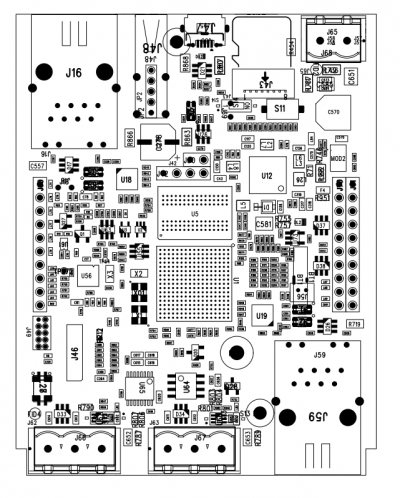
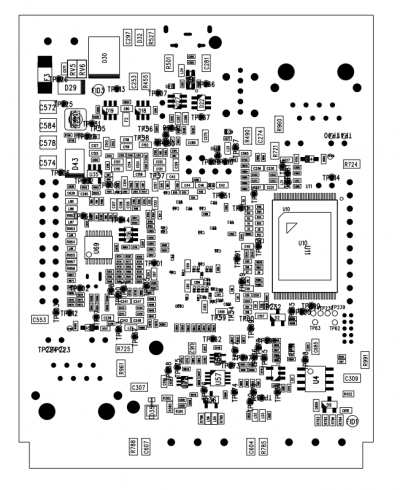
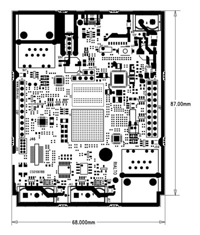
This page describes the mechanical characteristics of the RIALTO SBC board.
Board layout[edit | edit source]
Dimensions[edit | edit source]
CAD drawings[edit | edit source]
- STEP (3D): RIALTO.step
3D drawings[edit | edit source]
Mechanical data[edit | edit source]
| Dimension | Value |
|---|---|
| Width | 68 mm |
| Depth | 87 mm |
| Max component's height (top) | |
| Max component's height (bottom) | |
| PCB height |
