MITO 8M SOM/MITO 8M Hardware/pdf
General Information[edit | edit source]
MITO 8M SOM Block Diagram[edit | edit source]
[[File:Mito-bd-1.0.0-300dpi.png|thumb|MITO 8M Block diagram|none]]
MITO 8M SOM TOP View[edit | edit source]
[[File:DMI-Mito-top.png|thumb|MITO 8M TOP View|none]]
MITO 8M SOM BOTTOM View[edit | edit source]
[[File:DMI-Mito-bottom-300dpi.png|thumb|MITO 8M BOTTOM View|none]] {{#lst:MITO 8M SOM/MITO 8M Hardware/General Information/Processor and memory subsystem|Body}} {{#lst:MITO 8M SOM/MITO 8M Hardware/General Information/Hardware versioning and tracking|Body}} {{#lst:{{{nome-som}}} SOM/{{{nome-som}}} Hardware/SOM P/N composition|Body}}
Pinout Table[edit | edit source]
{{#lst:MITO 8M SOM/MITO 8M Hardware/Pinout Table |Body}}
Power and reset[edit | edit source]
{{#lst:MITO 8M SOM/MITO 8M Hardware/Power and Reset/Power Supply Unit (PSU) and recommended power-up sequence|Body}} {{#lst:MITO 8M SOM/MITO 8M Hardware/Power and Reset/Reset scheme and control signals|Body}} {{#lst:MITO 8M SOM/MITO 8M Hardware/Power and Reset/System boot|Body}} {{#lst:MITO 8M SOM/MITO 8M Hardware/Power and Reset/JTAG|Body}}
Peripherals[edit | edit source]
{{#lst:MITO 8M SOM/MITO 8M Hardware/Peripherals/Audio |Body}} {{#lst:MITO 8M SOM/MITO 8M Hardware/Peripherals/CAN|Body}} {{#lst:MITO 8M SOM/MITO 8M Hardware/Peripherals/Ethernet|Body}} {{#lst:MITO 8M SOM/MITO 8M Hardware/Peripherals/HDMI|Body}} {{#lst:MITO 8M SOM/MITO 8M Hardware/Peripherals/LVDS|Body}} {{#lst:MITO 8M SOM/MITO 8M Hardware/Peripherals/MIPI|Body}} {{#lst:MITO 8M SOM/MITO 8M Hardware/Peripherals/SDIOs|Body}}
Peripheral UARTs[edit | edit source]
Description[edit | edit source]
The Universal Asynchronous Receiver/Transmitter (UART) interface available on MITO 8M is based on iMX8M SoC.
UARTs provides serial communication capability with external devices and support NRZ encoding format, RS485 compatible 9 bit data format and IrDA-compatible infrared slow data rate (SIR) format.
The UART port supports the following standards and features:
- High-speed TIA/EIA-232-F compatible, up to Mbit/s
- Serial IR interface low-speed, IrDA-compatible (up to 115.2 Kbit/s)
- 9-bit or Multidrop mode (RS-485) support (automatic slave address detection)
- 7 or 8 data bits for RS-232 characters, or 9 bit RS-485 format
- 1 or 2 stop bits
- Programmable parity (even, odd, and no parity)
- Hardware flow control support for request to send (RTS_B) and clear to send (CTS_B) signals
- Two independent, 32-entry FIFOs for transmit and receive
Pin mapping[edit | edit source]
The Pin mapping is described in the Pinout table section
Peripheral USB[edit | edit source]
Universal Serial Bus (USB) is an industry standard that establishes specifications for cables and connectors and protocols for connection, communication and power supply (interfacing) between computers, peripherals and other computers.
Description[edit | edit source]
The two USB interface available on MITO 8M are based on iMX8M SoC.
Each USB 3.0-compliant serial interface port supports the following standards and features:
- USB dual-role operation and can be configured as host or device
- Super-speed (5 Gbit/s), high-speed (480 Mbit/s), full-speed (12 Mbit/s), and low-speed (1.5 Mbit/s) operations.
- OTG (on-the-go) 2.0 compliant, which includes both device and host capability. Super-speed operation is not supported when OTG is enabled.
Pin mapping[edit | edit source]
The Pin mapping is described in the Pinout table section
Peripheral PCI Express[edit | edit source]
PCI Express (Peripheral Component Interconnect Express) is a high-speed serial computer expansion bus standard, designed to replace the older PCI, PCI-X and AGP bus standards.
The two PCI Express interface on MITO 8M SOM:
- PCIe1 is avaiable on SODIMM connector pinout
- PCIe2 is avaiable on ONE PIECE expansion connector J5
Description[edit | edit source]
The PCI Express interfaces available on MITO 8M is based on iMX8M SoC.
The PCI Express interfaces supports the following standards and features:
- two PCIe PHY ports (1-lines each)
- up to 6.0 Gbps data rate
- complies to PCI Express base specification 2.1.
- 8B/10B Encoding / Decoding
- Supports Spread Spectrum Clocking in Transmitter and Receiver
Pin mapping[edit | edit source]
The Pin mapping is described in the Pinout table section
Peripheral GPIOs[edit | edit source]
The GPIO general-purpose input/output peripheral provides dedicated general-purpose pins that can be configured as either inputs or outputs.
Description[edit | edit source]
When configured as an output, it is possible to write to an internal register to control the state driven on the output pin. When configured as an input, it is possible to detect the state of the input by reading the state of an internal register. In addition, the GPIO peripheral can produce CORE interrupts.
Pin mapping[edit | edit source]
The Pin mapping is described in the Pinout table section
Real Time Clock[edit | edit source]
This chapter describes the technical specifications and features for the RTC component on the MITO 8M module.
The Real Time Clock available on MITO 8M is based on iMX8M SoC.
Features[edit | edit source]
The MITO 8M module uses a 32.768kHz dedicated crystal in order to obtain an accurate time base for the RTC.
Important note for RTC during power-off[edit | edit source]
On the MITO 8M module the SNVS voltage rails are obtained by the main supply of the SOM.
For this reason, there is no possibility to keep operative the CPU RTC when the SOM is not connected to the 3.3VIN power rail.
Use an external RTC with battery backup functionality if required.
Peripheral Watchdog[edit | edit source]
The Watchdog Timer (WDOG) protects against system failures by providing a method by which to escape from unexpected events or programming errors.
Description[edit | edit source]
By default, the Watchdog Timer of iMX8M SOC is internally used on MITO 8M for the CPU-initiated software reset function.
For more details see the reset scheme and control signals section.
Pin mapping[edit | edit source]
The Pin mapping is described in the Pinout table section
Electrical, Thermal and Mechanical Features[edit | edit source]
Operational characteristics[edit | edit source]
Maximum ratings[edit | edit source]
| Parameter | Min | Typ | Max | Unit |
|---|---|---|---|---|
| Main power supply voltage | 0 | 3.3 | 3.6 | V |
Recommended ratings[edit | edit source]
| Parameter | Min | Typ | Max | Unit |
|---|---|---|---|---|
| Main power supply voltage | 3.135 | 3.3 | 3.465 | V |
Power consumption[edit | edit source]
Providing theoretical maximum power consumption value would be useless for the majority of system designers building their application upon MITO 8M module. Practically speaking, these figures would be of no help when it comes to size power supply unit or to perform thermal design of real systems.
Instead, several configurations have been tested in order to provide figures that are measured on real-world use cases.
Please note that MITO 8M platform is so flexible that it is virtually impossible to test for all possible configurations and applications on the market. The use cases here presented should cover most of real-world scenarios. However actual customer's application might require more power than values reported here or customer's use case may be differ significantly with respect to the ones here considered.
Therefore, application-specific requirements have always to be taken into consideration in order to size power supply unit and to implement thermal management properly.
Use cases results[edit | edit source]
Measurements have been performed on the MITO 8M SOM under test is equipped with:
| Section not completed yet |
| Checkpoint | Power (mW) |
|---|---|
| U-boot prompt | xxxx |
| Linux prompt | xxxx |
| Stress App test (*) | xxxx |
(*) Stressful Application Test: https://github.com/stressapptest/stressapptest
Thermal management[edit | edit source]
The MITO 8M SOM is designed to support the maximum available temperature range declared by the manufacturer.
The customer shall define and conduct a reasonable number of tests and verification in order to qualify the DUT capabilities to manage the heat dissipation.
Any heatsink, fan etc shall be defined case by case.
DAVE Embedded Systems' team is available for any additional information, please contact sales@dave.eu.
Heatsink suggestion[edit | edit source]
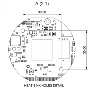
The MITO 8M SOM is designed with two holes that allow to mount a heatsink directly on the CPU IC.
Suggested part are ATS Push Pin Heat Sinks CPX0250250xx or FPX0250250xx part numbers.
See ATS website for more details [1].
Software thermal protection[edit | edit source]
In DESK-MX8-L, two software thermal protection mechanisms are implemented. Both are based on the processor's temperature sensor. It is worth remembering that maximum junction temperature (also denoted as Tj in the rest of the document) is:
- 95°C for Consumer parts
- 105°C for Industrial parts
| Section not completed yet |
U-Boot[edit | edit source]
At U-Boot level, automatic boot procedure is halted until Tj is smaller than (following temperatures might seem excessively low but they take into account the intrinsic poor precision of the temperature sensor to provide a reasonable safe margin):
- TBD for Consumer parts
- 95°C for Industrial parts
Linux kernel[edit | edit source]
At Linux level, a more sophisticated protection mechanism is implemented. Please refer to the following sections for more details.
The default temperature thresholds depend on the silicon grade, as follows:
- for Consumer parts
- passive threshold: TBD
- critical threshold: TBD
- for Industrial parts
- passive threshold: 85°C
- critical threshold: 95°C
Practically speaking, for DESK-MX8-L this mechanism makes use of two different thresholds, denoted as trip_point0 (also known as passive threshold) and trip_point1 (also known as critical threshold).
When Tj reaches trip_point0, Linux kernel scales down processor frequency.
If Tj reaches trip_point1, a complete shutdown is triggered:
thermal thermal_zone0: critical temperature reached(95 C),shutting down
By default, temperature thresholds are set up as follows:
trip_point0: 85°Ctrip_point1: 95°C.
Trip point thresholds can be accessed via sysfs interface from user space. The following example shows how to read the values of the trip points:
root@mito:~# cat /sys/devices/virtual/thermal/thermal_zone0/trip_point_0_temp
85000
root@mito:~# cat /sys/devices/virtual/thermal/thermal_zone0/trip_point_1_temp
950000
This example shows how to set trip points 0 and 1 to 95°C and 100°C respectively:
echo 95000 > /sys/class/thermal/thermal_zone0/trip_point_0_temp
echo 100000 > /sys/class/thermal/thermal_zone0/trip_point_1_temp
Please note that:
- it is possible to set up trip points greater than the maximum junction temperature indicated by manufacturer datasheet;
- exceeding maximum junction temperature indicated by manufacturer datasheet may cause permanent damage.
To read current processor temperature please issue this command (reported temperature is 36.676°C in the example):
root@mito:~# cat /sys/class/thermal/thermal_zone0/temp
36676
For more details about this functionality, please refer to Documentation/thermal/sysfs-api.txt in the kernel sources.
Mechanical specifications[edit | edit source]
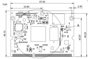
This chapter describes the mechanical characteristics of the MITO 8M module.
Board Layout[edit | edit source]
The following figure shows the physical dimensions of the MITO 8M module:
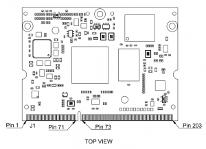
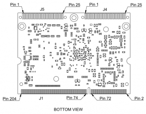
Connectors[edit | edit source]
The following figure shows the MITO 8M connector layout:
CAD drawings[edit | edit source]
- DXF (2D): CS031518.dxf
- STEP (3D): CS031518


